Vision
-
To empower students with skills aiming at self-sustained India in an informal learning environment.
Mission
- To encourage students to access equipment and tools under one roof to transform ideas into prototypes, through experiential learning in line with New Education Policy.
- To Promote “Do it Yourself and Do it with others culture” among the students of diverse disciplines by imparting 21st century skills.
- To strengthen the culture of Innovation, Incubation and Entrepreneurship.
- To enhance outreach with nearby Industries and Institutions through collaboration.
Team
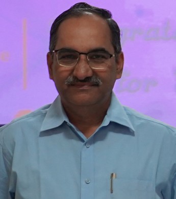 Dr. K. LAKSHMI PRASAD Chief Mentor |  Dr. V. MURALI KRISHNA Faculty Coordinator |  Dr. M. C. CHINNAIAH Faculty Co-Coordinator |  Dr. MUTHALUGU R Guru | 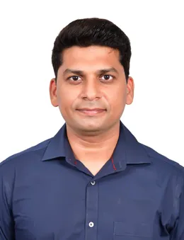 Mr. P. NARESH KUMAR REDDY Guru |  Mr. J. KISHORE Guru |  Mr. P. SUBRAMANYAM RAJU Guru |
Aion MK 500-FDM
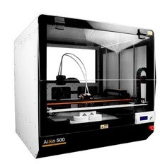
FDM (Fused Deposition Modeling) is a popular 3D printing technology that works by melting and extruding thermoplastic filament layer by layer to create a three- dimensional object.
Working:
FDM (Fused Deposition Modeling) is a popular 3D printing technology that works by melting and extruding thermoplastic filament layer by layer to create a three-dimensional object. Here’s how it works:
Model Creation: First, a 3D model is created using CAD (Computer- Aided Design) software or obtained from a 3D scanner
Slicing: The 3D model is sliced into thin horizontal layers using slicing software. Each layer’s data is then sent to the 3D printer
Printing Process: The 3D printer heats the thermoplastic filament to its melting point.
Applications:
FDM 3D printing: Enables rapid prototyping for engineers; Customizes medical devices; Enhances education and manufactures parts for industries.
Specifications:
| Description | Specifications |
| Model | Aion MK 500-FDM |
| Build Volume | 125litre |
| Maximum Printable Area | 500mm x 500mm x 500mm |
| Heated Bed | High performance heated bed 150W |
| Filament Diameter | 1.75mm |
| Extruder Diameter | 0.6mm/0.5mm/0.4mm |
| Extruder Temperature | 310⁰ C |
| Number Of Extruders | 2 |
| Recommended Materials | ABS, PLA, HIPS, PETG, Nylon, ASA etc. |
| Maximum Print Speed | 200mm/s |
| Material Deposition Rate | 15-30 cm³/hour |
| Layer Precision | 0.1-0.25mm (0.35mm possible for 0.5mm Nozzle) |
| Heat Bed Temperature | 90⁰ C (Max) |
| Positioning Accuracy | 20 microns |
| Total Machine Weight | 250Kg |
| Pause Print Option | Yes |
| Filaments Sensor | Yes |
CNC LASER ENGRAVING & CUTTING MACHINE

Computer Numeric Controlled (CNC) Laser cutting machines work on the principle that a focused high-power laser beam is used to cut, inscribe, or engrave a metal surface to get the desired shapes.
Working:
CO2 laser cutting utilizes a high-energy laser beam to precisely cut materials by heating and vaporizing them, without direct contact. Initially developed for non-metals, high-powered CO2 lasers can also cut metals. The laser’s energy is absorbed by the material, raising its temperature to burn, melt, or vaporize it. By adjusting factors like power, speed, and intensity, various materials can be cut effectively.
Applications:
CO2 laser cutting machines are indeed well-suited for prototyping and research and development activities, particularly for cutting and engraving non-metallic materials like acrylic, nylon, and wood.
Specifications:
| Description | Specifications |
| Model | MarkSys EC 13.9 Premium |
| Driven Type | Electric |
| Operation Mode | Semi-Automatic |
| Laser Tube | 1800-2200 Hours |
| Max Speed | 0-54000mm/min |
| Laser Type | CO2 Laser |
| Laser Power | 130W |
| Cutting Depth | 12mm |
| Work table | Honeycomb |
| Working Area | 1300mmX900mm |
| Applications | Engraving, Cutting |
| Method of Cooling | Water Cooling |
| Supporting Image Format | AL, BMP, PLT, DXF |
| Raw Materials | Acrylic, Glass, Handicraft cards, Leather, Paper, Plastic, Polymer composites, Resin, Textiles, Wood etc. |
Calibry mini 3D Scanner
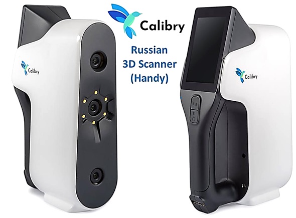
Calibry Mini 3D scanner is a handheld device that captures the shape and appearance of real-world objects through structured light technology, creating accurate digital 3D models. Known for its portability, accuracy, and ability to capture color textures.
Working:
3D scanner is a device that analyzes a real-world object or environment to collect data on its shape and appearance. It creates a digital representation of the object in three dimensions, often used for various applications such as reverse engineering, quality control, and digital archiving. In this technique, a structured light pattern, typically a grid or series of lines, is projected onto the object. The deformation of the
pattern on the object’s surface is captured by one or more cameras. Using principles of triangulation, the scanner calculates the object’s shape and creates a 3D model.
Applications:
CO2 laser cutting machines are indeed well-suited for prototyping and research and development activities, particularly for cutting and engraving non-metallic materials
like acrylic, nylon, and wood.
Specifications:
| Description | Specifications |
| Model | Calibry mini 3D scanner |
| Accuracy | Up to 0.07 mm |
| Accuracy over distance | Up to 0.1 mm over 1 m |
| Point Resolution | Up to 0.15 mm |
| Depth of view | 180 – 300 mm |
| Field of View | Min – 86×115 mmMax – 144×192 mm |
| Texture | Yes |
| Light Source | Blue LED |
| Frame Rate | 25 – 30 fps |
| Data Acquisition Speed | 3M points/sec |
| Multi-Core Processing | Yes |
| Weight | 900 gr (1.91 lb) |
| Touch Screen | Yes, 4 in |
| Operating Temperature | +5/+40C |
Working:
1.Designing: Operators create designs using CAD (Computer-Aided Design) software like Rhino3D, AutoCAD, SolidWorks, or SketchList3D. These designs specify the exact shapes and dimensions of the objects to be cut.
2.Conversion: Once the design is finalized, it is converted into CNC machine language using software such as Mach3, Nc- studio, Syntec, DSP, or Siemens. This language provides instructions for the CNC machine to follow during the cutting process.
3.Preparation: The wooden object to be cut is placed on the machine’s table, and screws are tightened to secure it firmly in place. This ensures stability during the cutting process.
4.Operation: With the object securely in place, the CNC wood router is started. The cutting tool, mounted on a motor, moves along three axes: X, Y, and Z. The X-axis allows horizontal movement, the Y-axis controls vertical movement, and the Z- axis controls the depth of the cut. The machine follows the instructions provided by the CNC software to precisely cut the wooden material according to the design.
5.Automation: The CNC wood router operates autonomously once the cutting process begins. It follows the programmed instructions without the need for continuous manual intervention.
6.Return to Origin: Before starting the cutting operation, the machine typically moves back to its origin position. This ensures that the cutting starts from a consistent point, enhancing accuracy and repeatability.
Overall, CNC wood routers offer efficiency, precision and consistency in woodworking tasks, making them invaluable tools in both industrial settings and workshops. Their automated operation allows operators to focus on other tasks while the machine completes the cutting process.
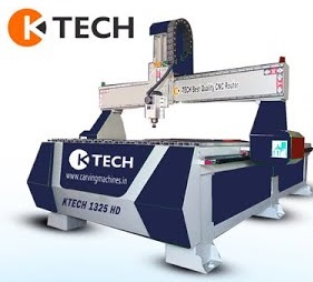
CNC WOOD ROUTER
A computer numerical control (CNC) router is a computer-controlled cutting machine which typically mounts a hand-held router as a spindle which is used for cutting various materials, such as wood, composites, metals, plastics, glass and foams.
Specifications:
| Description | Specifications |
| Model | K-Tech 1325HD |
| Table Size | 1300 mm x 3010 mm |
| X-Y Axis Working Area | 1300 x 2500 mm |
| Z Axis Working Area | 300 mm |
| Spindle Power | 3 kW |
| Job Material | Plastic, Acrylic, Sign Board |
| Spindle Head Type | Single Spindle |
| Maximum Cutting Speed | 35 m/min |
| Spindle Speed | 6000-24000 RPM |
| X-Y Movement | Rack & Pinion |
| Z movement | Lead Screw |
| Driven Motor | Stepper Motor |
| Power Consumption | 400 W |
| Applications | 2D Engraving, 3D Engraving and Cutting |
Working:
- Printed Circuit Board (PCB) machine is a sophisticated equipment used in the manufacturing of electronic circuit boards. The working principle involves several key steps.
- Design Phase: Initially, a schematic of the electronic circuit is created using CAD (Computer-Aided Design) software. This schematic is then converted into a PCB layout.
- Printing the Circuit: The PCB machine utilizes a process called PCB etching or lithography to print the circuit design onto a copper-clad board. This is typically done using a photoresist process, where a photosensitive material is applied onto the board, exposed to UV light through a stencil of the circuit pattern, and then chemically developed to remove the unexposed areas, leaving behind the circuit pattern.
- Etching: After printing, the exposed copper areas are etched away using chemical solutions, leaving only the desired copper traces that form the electrical connections of the circuit.
- Drilling: Holes are drilled into the board at specific locations to accommodate electronic components that will be soldered onto the PCB.
- Component Placement and Soldering: Electronic components such as resistors, capacitors, integrated circuits and connectors are placed onto the board according to the circuit design. The components are soldered onto the PCB to establish electrical connections. This can be done using wave soldering, reflow soldering or hand soldering techniques.
Applications:
- Consumer Electronics: PCB machines are vital for producing devices like smartphones, laptops, and TVs, ensuring their functionality
- Industrial Equipment: PCB’s power machinery control systems in manufacturing, improving productivity and quality control.
- Medical Devices: PCBs are crucial in patient monitoring and diagnostic equipment, ensuring accurate performance for patient care.
PCB DESIGNING & PROTOTYPING MACHINE
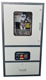
A PCB prototyping machine is a specialized device that automates the rapid and precise production of prototype printed circuit boards (PCBs), facilitating quick iteration and testing of electronic designs, ultimately reducing development time and costs.
Specifications:
| Description | Specifications |
| Model | AV-PCB-SA |
| Software | Copper CAM & Mach3 Mill |
| Resolution (X/Y) | 3.125 Micro Meter |
| Working Area (X/Y/Z) | 200x300x120 mm |
| Minimum Width Line & Space in mm | 0.1 (4 mm) |
| Max Travel Speed (mm/sec) | 58 (2.28 “) |
| Drilling (mm) | 0.2 -3.175 (8-125 mil) |
| Maximum Drilling Cycles/ Min | 50 |
| Feeding Height | 120 mm |
| Power | 220 V AC |
Aion MK 500-FDM

FDM (Fused Deposition Modeling) is a popular 3D printing technology that works by melting and extruding thermoplastic filament layer by layer to create a three- dimensional object.
Working:
FDM (Fused Deposition Modeling) is a popular 3D printing technology that works by melting and extruding thermoplastic filament layer by layer to create a three-dimensional object. Here’s how it works:
Model Creation: First, a 3D model is created using CAD (Computer- Aided Design) software or obtained from a 3D scanner
Slicing: The 3D model is sliced into thin horizontal layers using slicing software. Each layer’s data is then sent to the 3D printer
Printing Process: The 3D printer heats the thermoplastic filament to its melting point.
Applications:
FDM 3D printing: Enables rapid prototyping for engineers; Customizes medical devices; Enhances education and manufactures parts for industries.
Specifications:
| Description | Specifications |
| Model | Aion MK 500-FDM |
| Build Volume | 125litre |
| Maximum Printable Area | 500mm x 500mm x 500mm |
| Heated Bed | High performance heated bed 150W |
| Filament Diameter | 1.75mm |
| Extruder Diameter | 0.6mm/0.5mm/0.4mm |
| Extruder Temperature | 310⁰ C |
| Number Of Extruders | 2 |
| Recommended Materials | ABS, PLA, HIPS, PETG, Nylon, ASA etc. |
| Maximum Print Speed | 200mm/s |
| Material Deposition Rate | 15-30 cm³/hour |
| Layer Precision | 0.1-0.25mm (0.35mm possible for 0.5mm Nozzle) |
| Heat Bed Temperature | 90⁰ C (Max) |
| Positioning Accuracy | 20 microns |
| Total Machine Weight | 250Kg |
| Pause Print Option | Yes |
| Filaments Sensor | Yes |
CNC LASER ENGRAVING & CUTTING MACHINE

Computer Numeric Controlled (CNC) Laser cutting machines work on the principle that a focused high-power laser beam is used to cut, inscribe, or engrave a metal surface to get the desired shapes.
Working:
CO2 laser cutting utilizes a high-energy laser beam to precisely cut materials by heating and vaporizing them, without direct contact. Initially developed for non-metals, high-powered CO2 lasers can also cut metals. The laser’s energy is absorbed by the material, raising its temperature to burn, melt, or vaporize it. By adjusting factors like power, speed, and intensity, various materials can be cut effectively.
Applications:
CO2 laser cutting machines are indeed well-suited for prototyping and research and development activities, particularly for cutting and engraving non-metallic materials like acrylic, nylon, and wood.
Specifications:
| Description | Specifications |
| Model | MarkSys EC 13.9 Premium |
| Driven Type | Electric |
| Operation Mode | Semi-Automatic |
| Laser Tube | 1800-2200 Hours |
| Max Speed | 0-54000mm/min |
| Laser Type | CO2 Laser |
| Laser Power | 130W |
| Cutting Depth | 12mm |
| Work table | Honeycomb |
| Working Area | 1300mmX900mm |
| Applications | Engraving, Cutting |
| Method of Cooling | Water Cooling |
| Supporting Image Format | AL, BMP, PLT, DXF |
| Raw Materials | Acrylic, Glass, Handicraft cards, Leather, Paper, Plastic, Polymer composites, Resin, Textiles, Wood etc. |
Calibry mini 3D Scanner

Calibry Mini 3D scanner is a handheld device that captures the shape and appearance of real-world objects through structured light technology, creating accurate digital 3D models. Known for its portability, accuracy, and ability to capture color textures.
Working:
3D scanner is a device that analyzes a real-world object or environment to collect data on its shape and appearance. It creates a digital representation of the object in three dimensions, often used for various applications such as reverse engineering, quality control, and digital archiving. In this technique, a structured light pattern, typically a grid or series of lines, is projected onto the object. The deformation of the
pattern on the object’s surface is captured by one or more cameras. Using principles of triangulation, the scanner calculates the object’s shape and creates a 3D model.
Applications:
CO2 laser cutting machines are indeed well-suited for prototyping and research and development activities, particularly for cutting and engraving non-metallic materials
like acrylic, nylon, and wood.
Specifications:
| Description | Specifications |
| Model | Calibry mini 3D scanner |
| Accuracy | Up to 0.07 mm |
| Accuracy over distance | Up to 0.1 mm over 1 m |
| Point Resolution | Up to 0.15 mm |
| Depth of view | 180 – 300 mm |
| Field of View | Min – 86×115 mmMax – 144×192 mm |
| Texture | Yes |
| Light Source | Blue LED |
| Frame Rate | 25 – 30 fps |
| Data Acquisition Speed | 3M points/sec |
| Multi-Core Processing | Yes |
| Weight | 900 gr (1.91 lb) |
| Touch Screen | Yes, 4 in |
| Operating Temperature | +5/+40C |
Working:
1.Designing: Operators create designs using CAD (Computer-Aided Design) software like Rhino3D, AutoCAD, SolidWorks, or SketchList3D. These designs specify the exact shapes and dimensions of the objects to be cut.
2.Conversion: Once the design is finalized, it is converted into CNC machine language using software such as Mach3, Nc- studio, Syntec, DSP, or Siemens. This language provides instructions for the CNC machine to follow during the cutting process.
3.Preparation: The wooden object to be cut is placed on the machine’s table, and screws are tightened to secure it firmly in place. This ensures stability during the cutting process.
4.Operation: With the object securely in place, the CNC wood router is started. The cutting tool, mounted on a motor, moves along three axes: X, Y, and Z. The X-axis allows horizontal movement, the Y-axis controls vertical movement, and the Z- axis controls the depth of the cut. The machine follows the instructions provided by the CNC software to precisely cut the wooden material according to the design.
5.Automation: The CNC wood router operates autonomously once the cutting process begins. It follows the programmed instructions without the need for continuous manual intervention.
6.Return to Origin: Before starting the cutting operation, the machine typically moves back to its origin position. This ensures that the cutting starts from a consistent point, enhancing accuracy and repeatability.
Overall, CNC wood routers offer efficiency, precision and consistency in woodworking tasks, making them invaluable tools in both industrial settings and workshops. Their automated operation allows operators to focus on other tasks while the machine completes the cutting process.
CNC WOOD ROUTER
A computer numerical control (CNC) router is a computer-controlled cutting machine which typically mounts a hand-held router as a spindle which is used for cutting various materials, such as wood, composites, metals, plastics, glass and foams.

Specifications:
| Description | Specifications |
| Model | K-Tech 1325HD |
| Table Size | 1300 mm x 3010 mm |
| X-Y Axis Working Area | 1300 x 2500 mm |
| Z Axis Working Area | 300 mm |
| Spindle Power | 3 kW |
| Job Material | Plastic, Acrylic, Sign Board |
| Spindle Head Type | Single Spindle |
| Maximum Cutting Speed | 35 m/min |
| Spindle Speed | 6000-24000 RPM |
| X-Y Movement | Rack & Pinion |
| Z movement | Lead Screw |
| Driven Motor | Stepper Motor |
| Power Consumption | 400 W |
| Applications | 2D Engraving, 3D Engraving and Cutting |
Working:
- Printed Circuit Board (PCB) machine is a sophisticated equipment used in the manufacturing of electronic circuit boards. The working principle involves several key steps.
- Design Phase: Initially, a schematic of the electronic circuit is created using CAD (Computer-Aided Design) software. This schematic is then converted into a PCB layout.
- Printing the Circuit: The PCB machine utilizes a process called PCB etching or lithography to print the circuit design onto a copper-clad board. This is typically done using a photoresist process, where a photosensitive material is applied onto the board, exposed to UV light through a stencil of the circuit pattern, and then chemically developed to remove the unexposed areas, leaving behind the circuit pattern.
- Etching: After printing, the exposed copper areas are etched away using chemical solutions, leaving only the desired copper traces that form the electrical connections of the circuit.
- Drilling: Holes are drilled into the board at specific locations to accommodate electronic components that will be soldered onto the PCB.
- Component Placement and Soldering: Electronic components such as resistors, capacitors, integrated circuits and connectors are placed onto the board according to the circuit design. The components are soldered onto the PCB to establish electrical connections. This can be done using wave soldering, reflow soldering or hand soldering techniques.
Applications:
- Consumer Electronics: PCB machines are vital for producing devices like smartphones, laptops, and TVs, ensuring their functionality
- Industrial Equipment: PCB’s power machinery control systems in manufacturing, improving productivity and quality control.
- Medical Devices: PCBs are crucial in patient monitoring and diagnostic equipment, ensuring accurate performance for patient care.
PCB DESIGNING & PROTOTYPING MACHINE

A PCB prototyping machine is a specialized device that automates the rapid and precise production of prototype printed circuit boards (PCBs), facilitating quick iteration and testing of electronic designs, ultimately reducing development time and costs.
Specifications:
| Description | Specifications |
| Model | AV-PCB-SA |
| Software | Copper CAM & Mach3 Mill |
| Resolution (X/Y) | 3.125 Micro Meter |
| Working Area (X/Y/Z) | 200x300x120 mm |
| Minimum Width Line & Space in mm | 0.1 (4 mm) |
| Max Travel Speed (mm/sec) | 58 (2.28 “) |
| Drilling (mm) | 0.2 -3.175 (8-125 mil) |
| Maximum Drilling Cycles/ Min | 50 |
| Feeding Height | 120 mm |
| Power | 220 V AC |
AICTE-IDEA LAB
B. V. RAJU INSTITUTE OF TECHNOLOGY (AUTONOMOUS)
(NBA and NAAC Accredited, Approved By AICTE and Affiliated to JNTUH)
Vishnupur, Narsapur, Medak District – 502313
AICTE IDEA Lab Training Programs from April 2022 to May 2024
| S.NO. | Name of the Institution | Name of the Training Program | Dates/No of Days |
| 1. | Vishnu High School, Vishnupur, Narsapur. | Skilling program on 3D printing | 11thto 13th April 2022 |
| 2. | Ellenki Degree College Narsapur, Medak (Dist.) | Skilling program on 3D printing | 25th to 27th May 2022 |
| 3. | ZPHS Government High School Narsapur, Medak (Dist.) | Skilling program on 3D printing | 28th to 30thJune 2022 |
| 4. | B V Raju Institute of Technology, Narsapur (Students of all disciplines) | Skilling program on 3D printing | 07th to 09th July 2022 |
| 5. | Telangana Government Tribal Welfare Residential School – Girls, Narsapur | Skill Development Programme on Design Thinking and Additive Manufacturing | 17th to 19th August 2022 |
| 6. | Faculty members of B V Raju Institute of Technology, All disciplines | 6 Days Faculty Development Programme on Laser Cutting and Additive Manufacturing | 12th to 17th September 2022 |
| 7. | Alluri Seetharama Raju Telangana Government Tribal Welfare Residential School – Boys, Narsapur | Skilling Programme on Laser Engraving and Cutting | 21st to 23rd September 2022 |
| 8. | B V Raju Institute of Technology, Narsapur. (Students of all disciplines) | 27th to 29th September 2022 | |
| 9. | B V Raju Institute of Technology, Narsapur (Students of all disciplines) | 19th to 21st October 2022 | |
| 10. | B V Raju Institute of Technology, Narsapur (Students of all disciplines) | 26th to 28th October 2022 | |
| 11. | Techno Crats Private ITI (Affiliated to NCVT Govt. of India) | Two Weeks Professional Skilling Programme for ITI Students on Mechanical Fabrications | 14th to 26thNovember 2022 |
| 12. | B V Raju Institute of Technology, Narsapur (Students of all disciplines) | Two Weeks Boot Camp on Design Thinking and Advanced Manufacturing | 12th to 24thDecember 2022 |
| 13. | B V Raju Institute of Technology, Narsapur (Students of all disciplines) | 16th to 19thDecember 2022 | |
| 14. | B V Raju Institute of Technology, Narsapur (Students of all disciplines) | Skilling Programme on Advanced Manufacturing | 05th to 7th January 2023 |
| 15. | Vishnu High school, Vishnupur Narsapur. | Open Day for School Students | 21st January 2023 |
| 16. | B V Raju Institute of Technology, Narsapur (Students of all disciplines) | Skilling Programme on PCB Designing and Printing
| 25th to 28th January 2023 |
| 17. | B V Raju Institute of Technology, Narsapur (I B. Tech Students of all disciplines) | 5 Days Ideation Workshop | 06th to 10th February 2023 |
| 18. | B V Raju Institute of Technology, Narsapur (I B. Tech Students of all disciplines) | 5 Days Skilling Program on Building of Prototypes Using Advanced Manufacturing Technologies | 13th to 17th February 2023 |
| 19. | B V Raju Institute of Technology, Narsapur (I B. Tech Students of all disciplines) | Skilling program on Advanced Manufacturing and PCB Designing | 20th to 22nd February 2023 |
| 20. | Government Degree College, Narsapur, Medak (Dist) | Boot Camp on Ideation and Additive Manufacturing | 22nd to 24th February 2023 |
| 21. | Sri Vaishnavi Junior College, Narsapur, Medak (Dist) | Skilling Program on Advanced Manufacturing Machines | 25th to 28th February 2023 |
| 22. | B V Raju Institute of Technology, Narsapur. (Students of all disciplines) | Skilling Programme on Advanced Manufacturing and PCB Printing | 13th to 15th March 2023 |
| 23. | Vishnu High School, Narsapur, Medak (Dist), TS | 6 days teachers awareness program on Advanced Manufacturing Machines | 16th to 23rd March 2023 |
| 24. | Vijaya Lakshmi Private ITI, Narsapur, Medak (Dist), TS (Students of Fitter discipline) | Two Weeks Professional Skilling Program for ITI Students on Mechanical Fabrications and PCB Prototyping | 27th to March to 12th April 2023 |
| 25. | B V Raju Institute of Technology, Narsapur. (Students of all disciplines) | AICTE Idea Lab skilling program on Design & Manufacturing of Prototypes | 21st to 25th April 2023 |
| 26. | Vijaya Lakshmi Private ITI, Narsapur, Medak (Dist), TS (Students of Electrician discipline) | One Week Professional Skilling Program for ITI Students on design Thinking & Prototyping | 04th to 10th May 2023 |
| 27. | B V Raju Institute of Technology, Narsapur. (Students of all disciplines) | 6 Days Skilling Program on Design Thinking & Manufacturing of Micro Robots | 19th to 25th May 2023 |
| 28. | B V Raju Institute of Technology, Narsapur. (Students of all disciplines) | One Week Skilling Program on PCB Design and Fabrication | 05th to 09th June 2023 |
| 29. | Government Resedential ITI, Hathnura, Sangareddy Dist. | Two Weeks Professional Skilling Program for ITI students on Advanced Manufacturing & PCB Prototyping | 05th to 17th June 2023 |
| 30. | PN. Reddy High School, Nalanda Vidyalayam Narsapur | Awareness workshops on Design Thinking and Building of Prototypes | 21st to 23rd June 2023 |
| 31. | B V Raju Institute of Technology, Narsapur. (Students of different disciplines) | Skilling Program on Design Thinking and Prototyping | 22nd to 24th June 2023 |
| 32. | B V Raju Institute of Technology, Narsapur. (Students of different disciplines) | Skilling Program on Smart Manufacturing and Prototyping | 28th June to 3rd July 2023 |
| 33. | B V Raju Institute of Technology, Narsapur. (Students of different disciplines) | Skilling Program on Design Thinking and Advanced Manufacturing | 05th to 07th July 2023 |
| 34. | B.V. Raju Institute of Technology, Narsapur. | Skilling Program on Digital Manufacturing | 11th to 13th July 2023 |
| 35. | Government Junior College, Narsapur, Medak Dist. | Professional Skilling Program on 3D Printing and Laser Cutting | 19th to 21st July 2023 |
| 36. | Technocrat ITI, Narsapur, Medak Dist. | Professional Skilling Program on Advanced Manufacturing Machines | 07th to 12th August 2023 |
| 37. | Ellenki Degree College Narsapur, Medak Dist. | Professional Skilling Program on CNC Laser Engraving & cutting and 3D Printing | 28th to 30th August 2023 |
| 38. | B.V. Raju Institute of Technology, Narsapur. | Skilling Program on Advanced Manufacturing | 20th to 22nd September 2023 |
| 39. | Ellenki Junior College | Skilling Program on Digital and Advanced Manufacturing | 05th to 07th October 2023 |
| 40. | Government Polytechnic College Gomaram | Skilling Program on Prototyping Using Advanced Manufacturing Machines | 02nd to 04th November 2023 |
| 41. | Ratnapuri Institute of Technology-College of Polytechnic | Skilling Program On Advanced Manufacturing Techniques for Fabrication of Prototypes | 16th to 18th November 2023 |
| 42. | B.V. Raju Institute of Technology | Skilling Program on Design Thinking and Advanced Manufacturing | 21st to 26th November |
| 43. | ZPGHS Narsapur | Skilling Program on Advanced Manufacturing | 06th to 08th December 2023 |
| 44. | Vishnu High School | 11th to 13th December 2023 | |
| 45. | B.V. Raju Institute of Technology | Design Thinking and Digital Manufacturing | 19th to 21st December 2023 |
| 46. | B.V. Raju Institute of Technology | Design Thinking and Prototyping | 28th to 30th December 2023 |
| 47. | Ratnapuri Institute of Technology-College of Polytechnic | Skilling Program On Advanced Manufacturing Techniques for Fabrication of Prototypes | 04th to 06th January 2024 |
| 48. | Technocrats Private ITI, Narsapur, Medak Dist. | Professional Skilling Program on Advanced Manufacturing | 01st to 08th February 2024 |
| 49. | ZPGHS Narsapur | Open Day for School Students | 19th February 2024 |
| 50. | B.V. Raju Institute of Technology | Skilling Program On 3d Scanning And 3D Printing For Bio Medical Applications | 19th to 21st February 2024 |
| 51. | B.V. Raju Institute of Technology | Skilling Program on Advanced Manufacturing Machines | 22nd to 24th February 2024 |
| 52. | B.V. Raju Institute of Technology | Skilling Program on Design and Digital Manufacturing | 22nd , 23rd & 30th April 2024 |
| 53. | Summer Boot Camp for Rural Government School Students , Medak District, Telangana. | Skilling Program on Design Thinking and Digital Manufacturing | 07th, 09th & 10th May 2024 |
Projects completed by using AICTE-IDEA Lab
| S.No. | Nature of Project | Name of the coordinator | Name of the Project Guide | Title of the Project | Stream of the project (Programme) |
| 1 | Prototype making | Dr. V. Murali Krishna | Pandurang Mirajkar | Automatic height adjustable stand for document scanning | Automation |
| 2 | Prototype making | K S SAI KOUSHIK | NARESHKUMAR REDDY PALLELA | Robotic arm for pick and place application | Robotics |
| 3 | Prototype making | K. Rushali | R.Anirudh Reddy | Conversion of Algae to bio fuel | Bio Fuel |
| 4 | Prototype making | KAKUMANU JYOTHIRLATHA | Rohith Sirpa | Autism Spectrum Analysing Device | visual and cognitive processing |
| 5 | Prototype making | Palani Pawan Teja | Pandurang Mirajkar | Ballie Math Tool | Math Tool |
| 6 | Prototype making | BANALA SUKESH | Dr.A.Padma Rao | Robotic Vacuum Dry and Wet Mop Device | Robotics |
| 7 | Prototype making | THALLAPALLI VIVEK KUMAR GOUD | Dr. V. Murali Krishna | Fabrication of stair Climbing rover | Robotics |
| 8 | Prototype making | MANGALI HARIKUMAR | Mr.Waseem Ahamed | Gesture Controlled Robot | Robotics |
| 9 | Prototype making | BONTHIREDDYGARI NITHISH REDDY | Mr. Manzoor Hadi | Obstacle Avoiding Device Using Arduino | Arduino |
| 10 | Prototype making | JANGAM VIVEK | NARESHKUMAR REDDY PALLELA | Direction Controlled Robot Using Android Application | Robotics |
| 11 | Prototype making | KESHIREDDY SOUMYA SREE | Mr.R. Muthalagu | DIY Arduino- Powered Metal Detector Robot | Robotics |
| 12 | Prototype making | ADITYA R ARYAMAAN | Mr.R. Muthalagu | Path Trailing Carrier System | Robotics |
| 13 | Prototype making | MALKANI HARIPRASAD GOUD | Mr.P. Sangamesh | Mini Servo Robotic Arm | Robotics |
| 14 | Prototype making | GUNNALA TARUN REDDY | Dr. M. Sandeep Kumar | Voice Controlled Robot | Robotics |
| 15 | Prototype making | MOHAMMAD SUMEER | Dr. A. Varun | Quadcopter Drone | Drone |
On 31st July 2024, an expert team from AICTE visited the AICTE IDEA LAB at BVRIT-Narsapur. The visit aimed to assess the facilities and innovations taking place at the lab. This visit provided an opportunity for the team to interact with students, faculty, and researchers to understand the projects and initiatives being undertaken. The exchange of ideas and knowledge during this visit would likely contribute to the enhancement of the educational experience at BVRIT. The photographs captured during the visit would serve as a visual record of the insightful interactions and technological advancements witnessed by the AICTE team.
